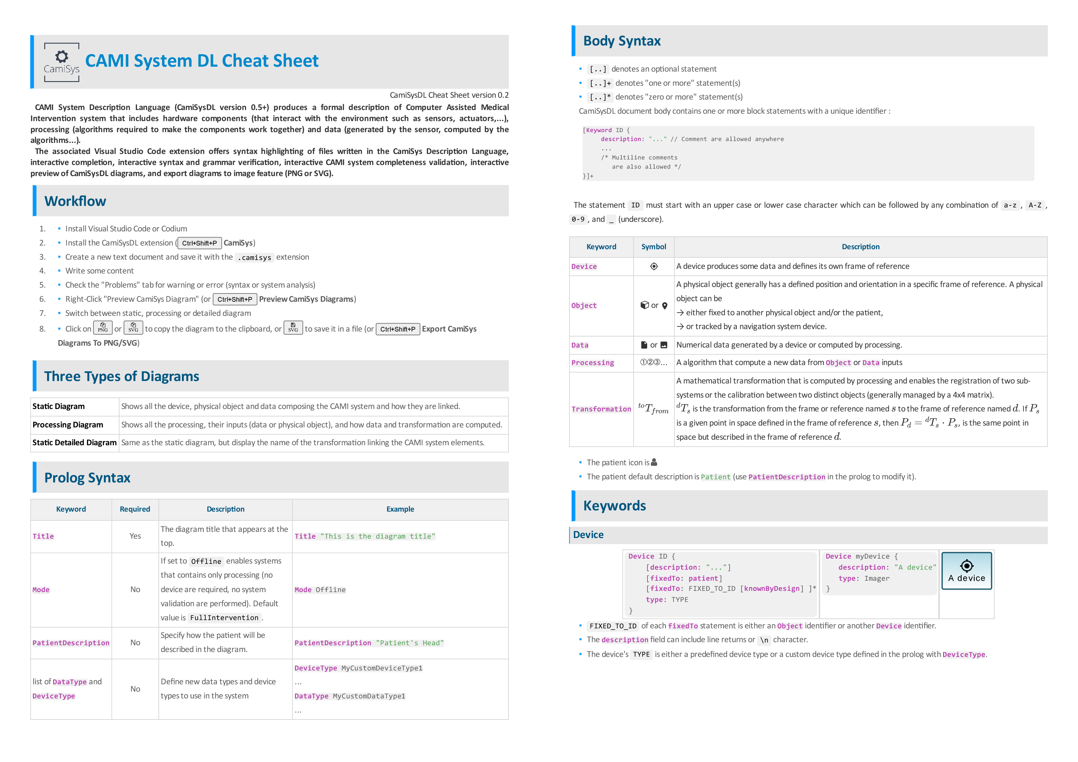
 CAMI System Description Language (CAMISysDL)
This is the visual code extension for the Computer Assisted Medical Intervention System Description Language (CAMISysDL).
CAMISysDL is designed to:
- produces a formal description of Computer Assisted Medical Intervention system that includes hardware components that interact with the environment (sensor, actuator, display...), software components (algorithm required to make the components work together) and data (acquired by the sensor, produced by algorithms...).
- automatically generates diagram representations or the system
The CAMISysDL diagrams should be able to describe any type of system used in Computer Assisted Medical Intervention or Computer Assisted Surgery.
This extension is made possible by
- Langium: an open source language development tool, probably the best around.
- PlantUML: an open-source language initially made to represent UML diagrams, now extremely versatile, coupled with a server to generate diagram from PlantUML statement on the fly.
Features
- Syntax highlighting and interactive completion editing CamiSysDL language
- Interactive syntax and grammar verification
- Interactive CAMI system completeness validation
- Interactive update of CamiSysDL diagrams
- Export diagrams to images (PNG or SVG)
Targeted users
The objective of CAMISysDL is to uniformize and simplify the description of CAMI systems using diagrams that describe the device, data and algorithms of a CAMI system.
The targeted users include students, engineer and researcher of the Computer Assisted Medical Intervention field.
Getting started
The easiest way to create CAMISysDL diagrams is to use this extension.
- Create a new file with the
.camisysextension - Copy-paste the example below
- Right click in your editor and launch the
Preview CamiSys Diagramsaction. Three types of diagrams are generated (click on the corresponding tab in the generated view to switch between diagrams):- "Static Diagram" shows all the elements composing the CAMI systems and how they are linked,
- "Processing Diagram" shows all the processing and how data and transformation are computed,
- "Static Detailed Diagram" shows a detailed view of the static diagram with the transformation names.
- The diagrams are updated interactively
- You can export your diagrams with the
Export CamiSys Diagrams To PNGandExport CamiSys Diagrams To SVGactions at any time - There are three icons in the diagram view to copy the current diagram in the clipboard (as PNG or SVG) and save the SVG diagram as an independant file.
Language Cheat Sheet
Download the CamiSys DL cheat sheet
Example
The following example is based on the description of a Image Guided Surgery for Brain Tumors CAMI system by Dr. Chris McPherson in this video (Image Guided Surgery for Brain Tumors at the Mayfield Brain and Spine clinic in Cincinnati, Ohio, USA).
Create a new file named test.camisys, and copy-paste the following lines in a file named and right-click to generate the diagrams.
Title "IGS brain tumor Mayfield hospital"
PatientDescription "head"

/*
 * pre-operative imaging of the patient's brain
 */
Device mri {
  description: "Magnetic Resonance
Imaging"
  type: MRImager
}

Data mriImages {
  description: "Pre-operative\nImages"
  type: Image3D
  generatedBy: mri calibratedByDefault
}

/*
 * Intra-operative space describing the navigation system
 */
Device polaris {
  description: "Camera\n(optical tracker)"
  type: Localizer
}

Object frameRB {
  description: "Reference Frame\n(rigid body\nfixed on table)"
  trackedBy: polaris
}

Object pointerRB {
  description: "Pointer\n(rigid body)"
  trackedBy: polaris
}

Object probeTip {
  description: "Probe's tip"
  fixedTo: pointerRB
}


// Note : if the head rest frame
// is not fixed to the patient's head,
// patient's head movement cannot be tracked into
// account during the procedure.
Object headRest {
  description: "Head rest\n(immobilizing patient's head)"
  // Note : uncomment the next line to see how
  // the diagram highlight the fact the patient's
  // head is not tracked during the procedure
  fixedTo: patient
  fixedTo: frameRB knownByDesign
}

Object fiducials {
  fixedTo: patient
}

/*
 * For the CAMI system to work, the pre-operative and per-operative
 * spaces have to be registered.
 *
 */

// Step 1: pre-operative image segmentation
// the positions of the fiducial in the images are segmented
Processing segmentation {
  description: "manual picking"
  returnType: Point
}

Data segmentedFiducials {
  type:PointSet
  computedBy: segmentation(mriImages)
}

// Step 2: pointer/probe tip calibration
Processing calibration {
  description: "pivot point\ncalibration"
  returnType: Transform
}

// Note: Without the following transformation the calibration
// is unknown and the transformation between tip and pointer
// appears in orange in the diagram
Transformation {
  from: probeTip
  to: pointerRB
  // Note: This is a simplification, calibration requires an additionnal calibration object
  computedBy: calibration(pointerRB)
}

// Step 3: digitization of the fiducials in per-operative space
// Now that the position of the tip in the per-operative space
// is known, acquire the position of the fiducial in the
// per-operative space
Processing fiducialsDigitization {
  description: "fiducials digitization"
  returnType: PointSet
}

Data digitizedFiducials {
  type: PointSet
  computedBy: fiducialsDigitization(probeTip, fiducials)
}

// Step 3: registration using the fiducials
// register the pre-operative and per-operative frame of references
// using a geometric rigid registration
Processing registration {
  description:"Geometric rigid\nregistration\n(Arun algorithm)"
  returnType: Transform
}

// Note: without this last transformation there are still two isolated sub systems.
// The static diagram shows two different
// unlinked subsystems, highlighting an inoperative CAMI system.
Transformation {
  from: segmentedFiducials
  to: digitizedFiducials
  computedBy: registration(segmentedFiducials,digitizedFiducials)
}
PlantUML server
The diagrams are generated from PlantUML code and requires a PlantUML server to generate the previews, PNG and SVG images.
By default the PlantUML project server is used as it is automatically available. It is recommended to install and use a local PlantUML server in order to increase generation speed and confidentiality. Once installed, go to this extension settings and change the camiSystem.plantUMLServer property URL accordingly.
For example if you have docker installed on your machine, you can very easily run a local PlantUML server using plantuml-server docker image:
- Type
docker run -d -p 8080:8080 plantuml/plantuml-server:jettyin a shell, - and change
camiSystem.plantUMLServertohttp://localhost:8080.